GNSS Timing Under Jamming: Why PPS Shifts and How to Stop It
The Short Answer
GNSS timing under jamming is a different problem from positioning under jamming, and the dangerous part is that it is silent. A jammer can shift a receiver’s 1PPS output while the position stays fixed and nothing in the status display looks wrong. The cause is frequency-dependent delay in the antenna and receiver analog chain: when part of the spectrum is masked, the receiver combines a different set of signals, and the delay that applies to the timing solution changes with it. Septentrio’s answer is in-band zero-delay anti-jamming — clean the jammed band instead of discarding it, so the PPS position never moves. In an urban test against a DJI jammer gun, Septentrio mosaic mini hardware held 100 % of RTK Fix solutions inside 1 cm and every position inside 2 m, with the PPS stable throughout the interference window.
Talk to an engineer about timing integrity
Tell us the band, the environment and the PPS or time budget you have to hold, and we will recommend a receiver configuration and price it. Request a quote — or email sales@gnss-solutions.com with your requirements.
Image courtesy of Septentrio
Why time is the failure nobody notices
GNSS delivers two products, not one: position and time. Position errors are visible — a surveyor sees the solution degrade, a machine operator sees the blade cut wide, an integrator sees the RTK flag drop. Time errors are not. A receiver that is 300 ns late still emits a clean, perfectly shaped PPS, and its own quality indicators still say the pulse is precise.
That matters because a growing share of critical infrastructure is disciplined to GNSS time rather than to GNSS position: 5G and 5G-A base station phase sync, grid phase measurement, financial transaction timestamps, data centre time, broadcast references. In each of those systems the receiver is the reference, and a reference that is quietly offset propagates that offset to everything downstream. Our GNSS receivers for precision timing and resilient PNT are specified around exactly this failure mode, and it is also why timing receivers are chosen for PPS stability rather than for metre-level position alone.
Jamming and spoofing: two threats, one wrong assumption
Jamming injects RF noise inside the GNSS bands, with the aim of masking the signals arriving from the satellites. Spoofing injects counterfeit GNSS-like signals in order to overpower and replace the genuine ones.
The widely held belief is that the two sit at different levels of severity: jamming is a denial of service — the signals are masked, so you lose the GNSS second pulse — while spoofing is the dangerous case, because the PPS still looks valid while actually being wrong.
That belief is only half true. Handled badly, an ordinary jammer — no spoofing involved at all — can shift the PPS as well.
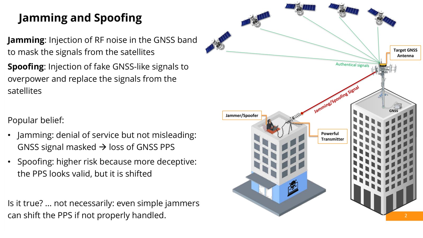
Image courtesy of Septentrio
What jamming does to a receiver: two layers
Position: the wanted signals are overpowered
Jamming means you either stop receiving the signals or stop receiving them accurately. Carrier-to-noise density (C/N0) falls across the affected bands, and if the interference is strong enough the receiver loses satellite tracking altogether.
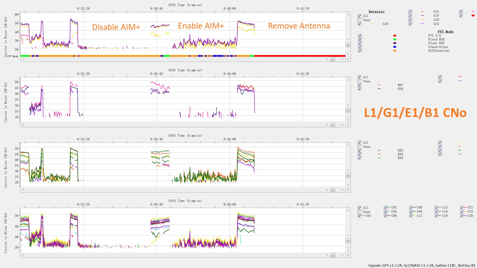
Image courtesy of Septentrio
Time: the PPS moves without announcing it
The timing layer behaves differently. The receiver keeps producing PPS throughout, and its performance indicators look normal — the reported PPS precision does not degrade. What does change is the position of the pulse in time: during the interference window the PPS is offset.
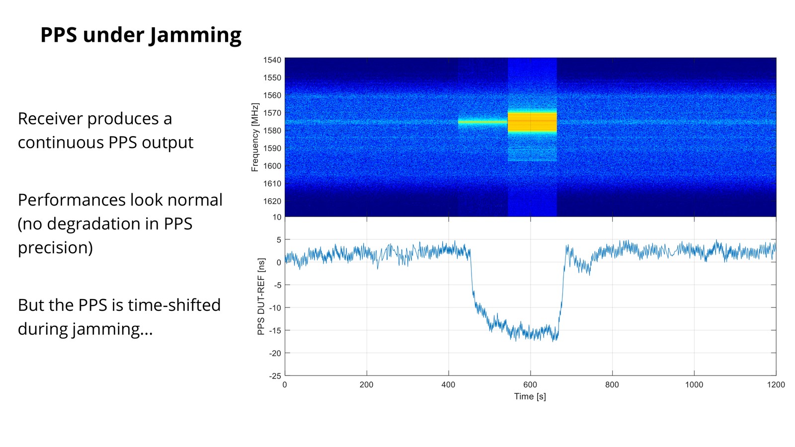
Image courtesy of Septentrio
Root cause: delay is not the same in every band
GNSS receivers do not use one signal; they use a combination of signals drawn from several frequency bands, which is what gives them robustness in normal conditions.
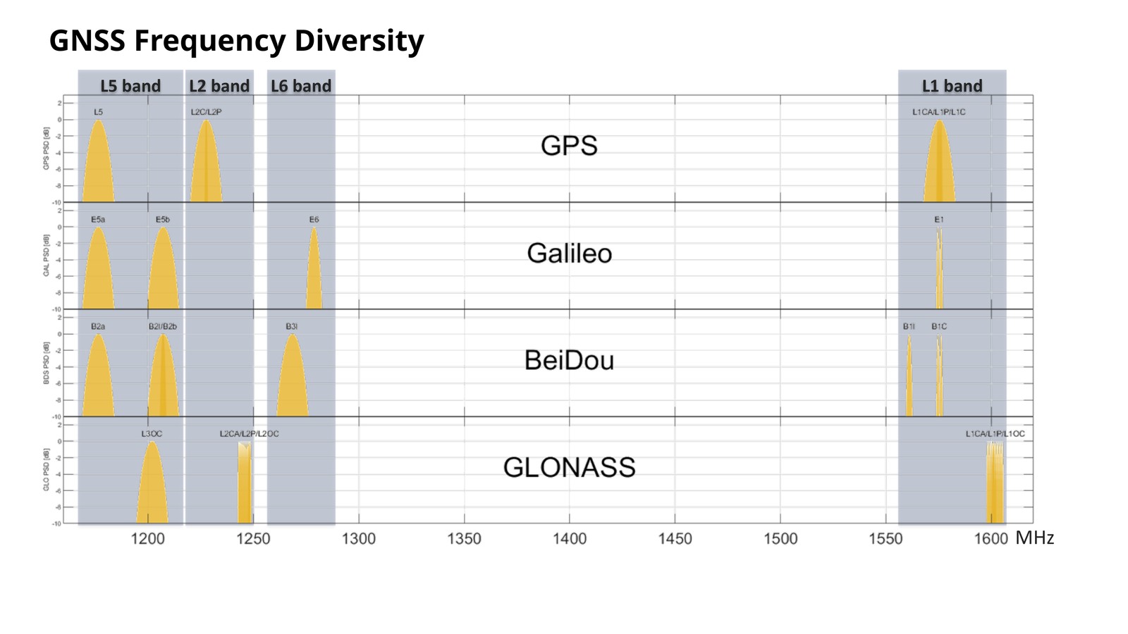
Image courtesy of Septentrio
Every analog component in the chain — antenna filters, amplifiers — introduces delay that depends on frequency. The group delay of an antenna filter is not constant across a band, and neither is the delay through the receiver front end. When a band is jammed, the set of signals that takes part in the combination changes, and the delay that applies to the processing chain changes with it.
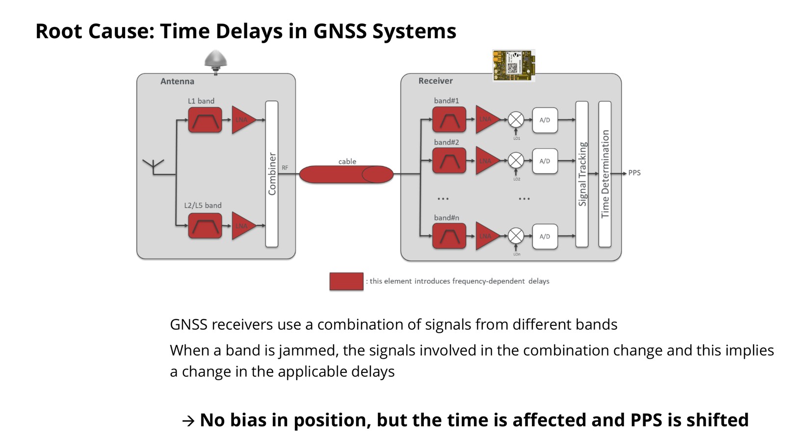
Image courtesy of Septentrio
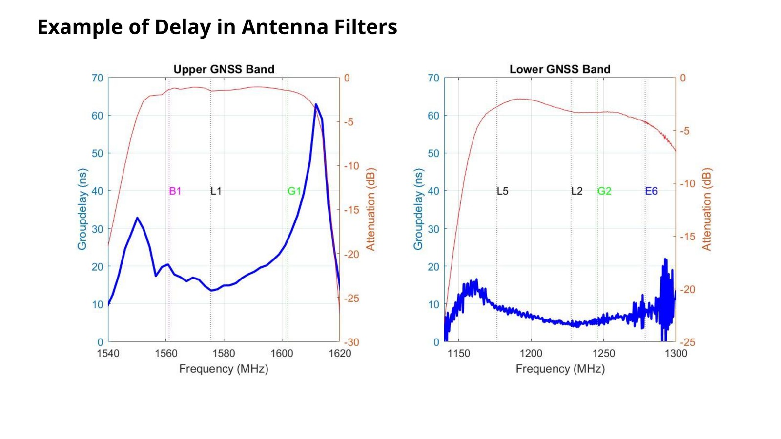
Image courtesy of Septentrio
The fix: in-band zero-delay anti-jamming — clean, do not discard
The conventional approach to interference is frequency diversity: detect the interference and switch away to a different set of signals. Switching works for position, but every switch also changes the delay that applies to the timing solution, which is exactly how a non-negligible PPS bias is introduced. Septentrio’s approach keeps every band in play and cleans the one that is being jammed:
- Real-time calibration, carried out in a jammer-free environment;
- No switching between different sets of signals;
- In-band zero-delay anti-jamming: cleaning instead of discarding the affected frequency band;
- Only constant-delay filters are used, with delay compensation applied;
- Linear-phase filters, which give a deterministic and constant delay.
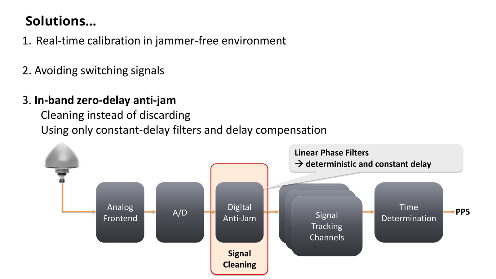
Image courtesy of Septentrio
The effect of cleaning is visible in the RF spectrum. Before the anti-jam module the interference is obvious; after it, the interference is gone and only the background noise remains.
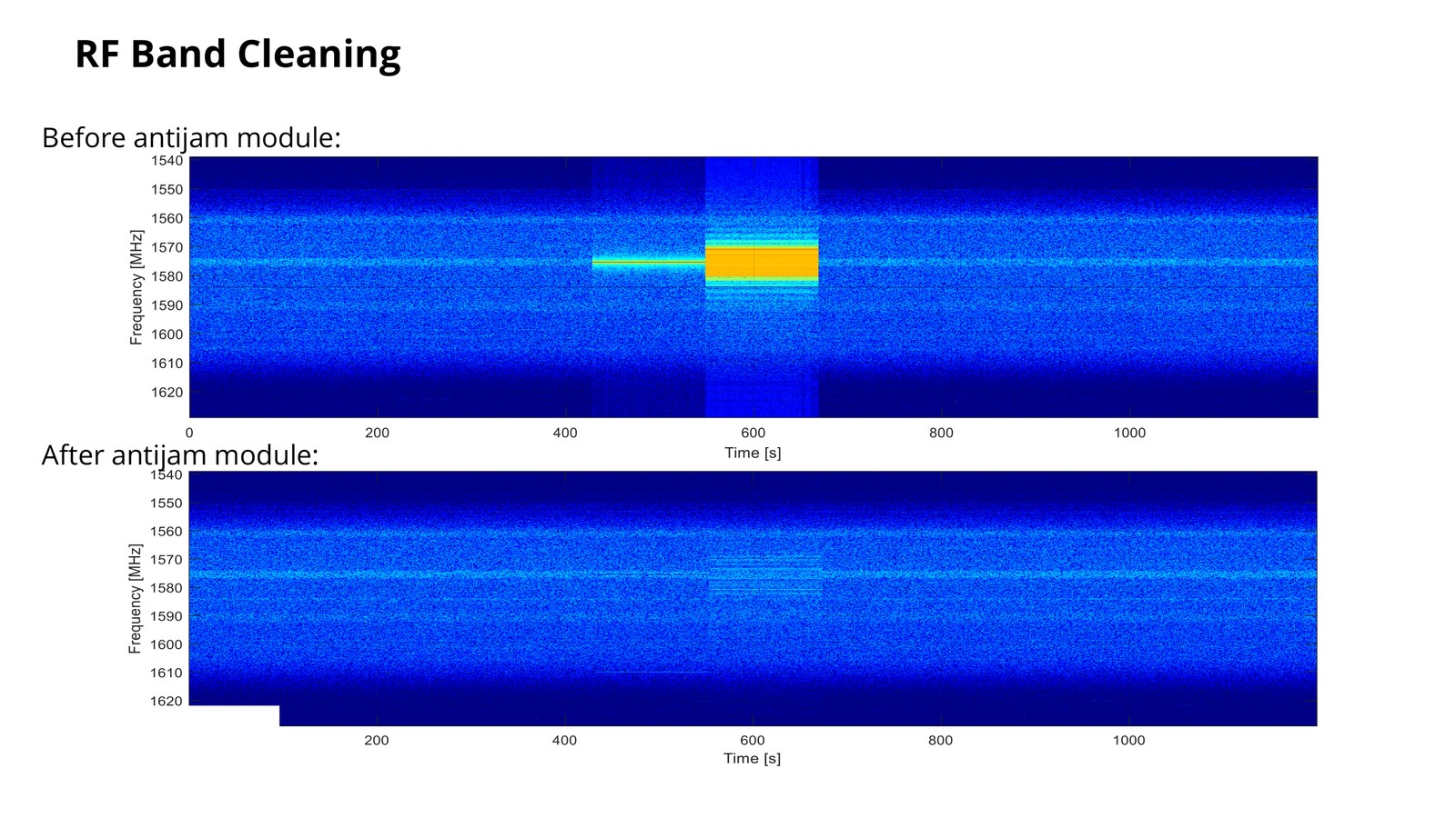
Image courtesy of Septentrio
Because there is no need to switch to other signals while the jammer is active, the PPS position stays stable.
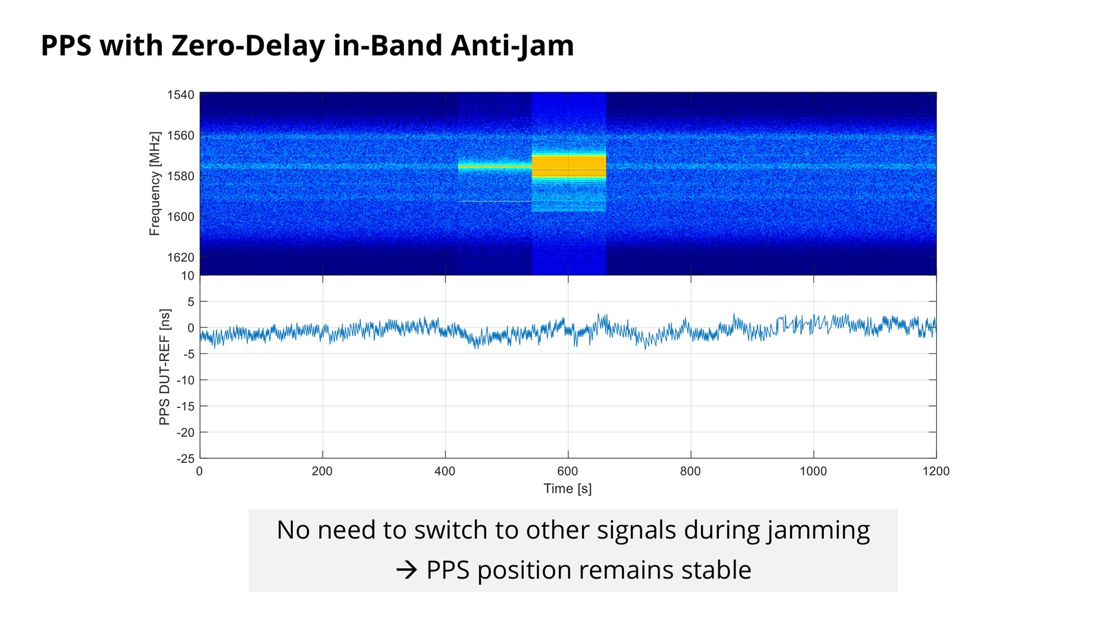
Image courtesy of Septentrio
| Traditional frequency diversity | In-band zero-delay anti-jamming | |
|---|---|---|
| Jammed band | Discarded — receiver switches to another set of signals | Kept and cleaned internally |
| Delay behaviour | Changes with the signal combination | Constant, filter-compensated, calibrated in real time |
| PPS during jamming | Can be offset, with no warning in the status display | Stays in place |
| Configuration | Re-selection logic triggered by interference | Real-time calibration in a jammer-free environment |
Field test: a DJI jammer gun against Septentrio mosaic hardware in a city centre
The behaviour above is not a simulation. In a downtown test, a DJI GNSS jammer gun was fired at mosaic (mini) hardware carrying AIM+, with the receiver logging raw data to an internal TF card.
Test setup
- Device under test: mosaic mini
- Antenna: Novatel full-band antenna
- Location: city centre, near the DJI office
- Interference source: DJI GNSS jammer gun
- Distance: 5–8 m, on the other side of the road
- Data recording: internal TF card
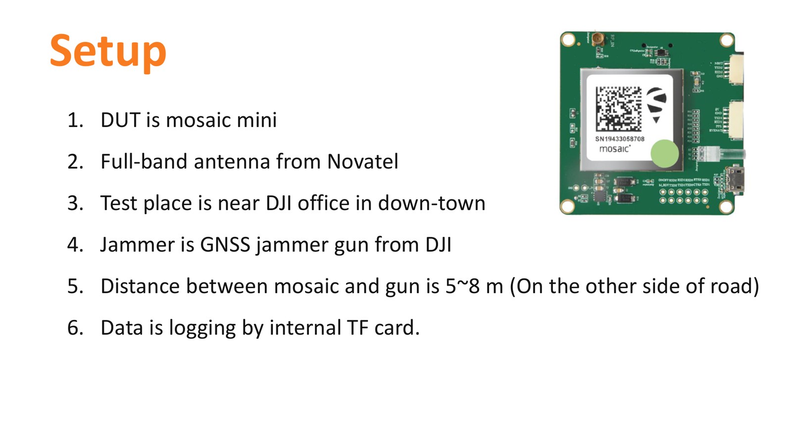
Image courtesy of Septentrio
Spectrum: with interference, then cleaned
With the jammer transmitting, the L1 band shows three strong interference peaks, at approximately 1563, 1575 and 1602 MHz. With AIM+ enabled, those peaks are removed and only background noise is left.
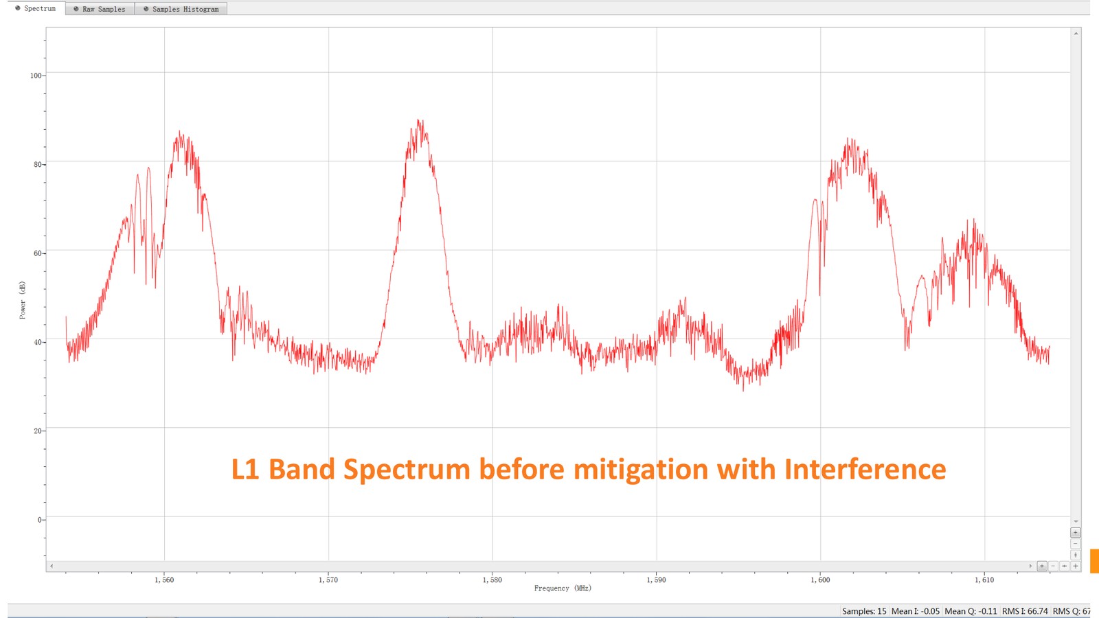
Image courtesy of Septentrio
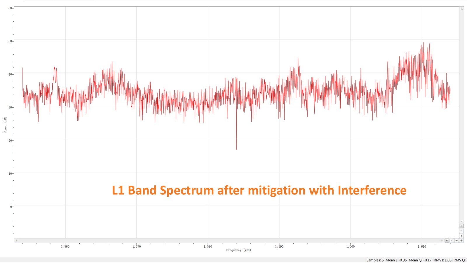
Image courtesy of Septentrio
C/N0 per band
The interference was concentrated in the L1/B1/G1 bands. With AIM+ disabled, C/N0 on those bands is suppressed and unstable; enabled, it returns to a stable level. Bands away from the jammer, such as L5 and the L2C/E5a/B2 group, are affected very little.
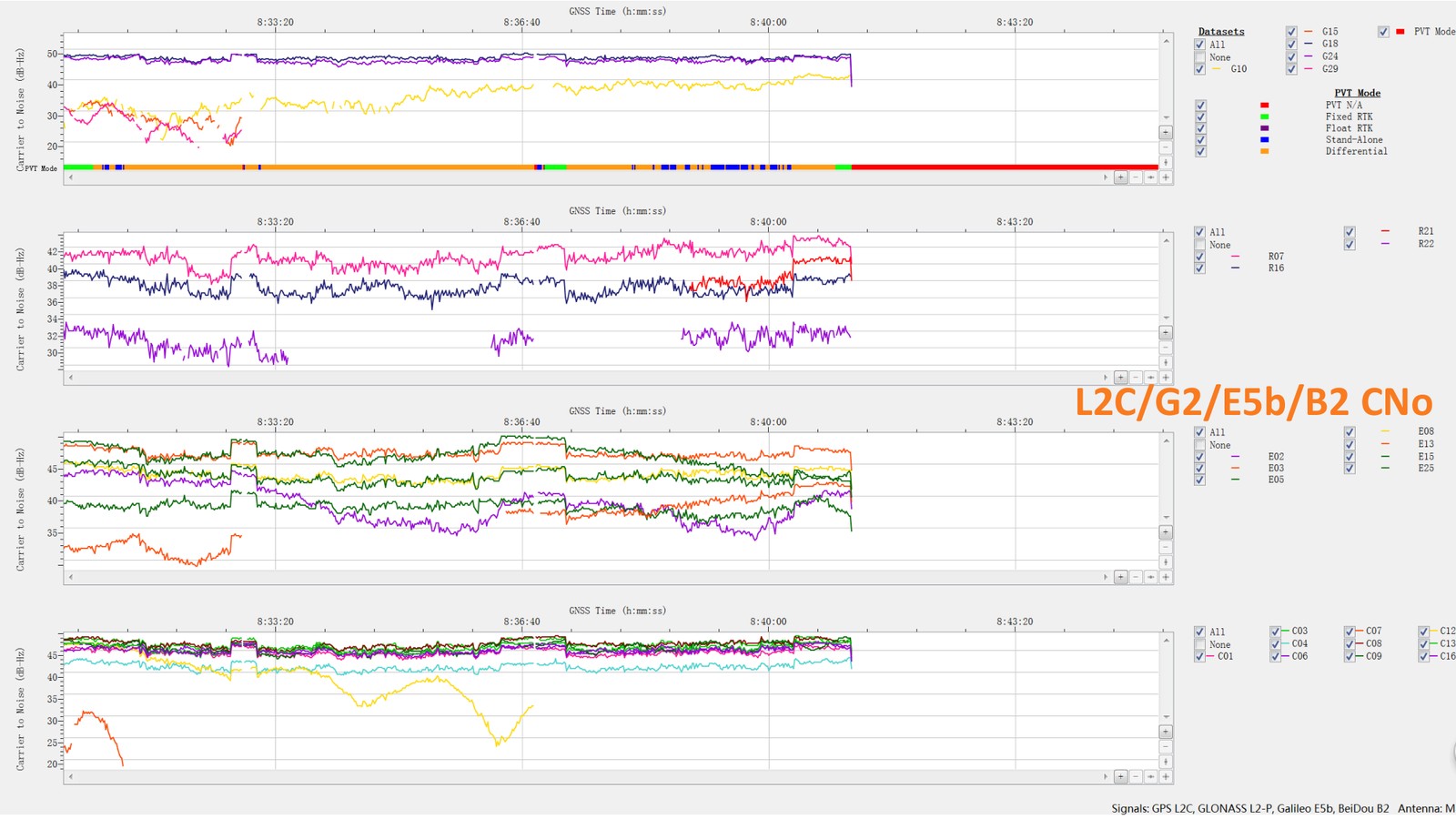
Image courtesy of Septentrio
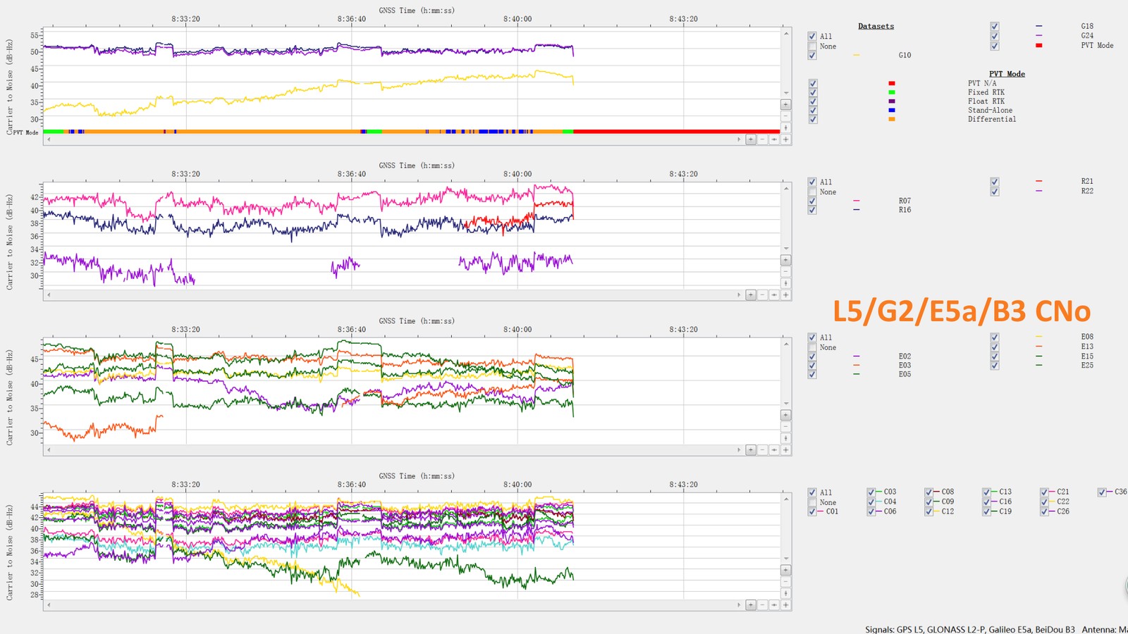
Image courtesy of Septentrio
Gain per band
Gain tells the same story from the front-end perspective. With AIM+ disabled, gain on the affected L1/G1 bands swings violently and even touches the noise floor; with AIM+ enabled it settles.
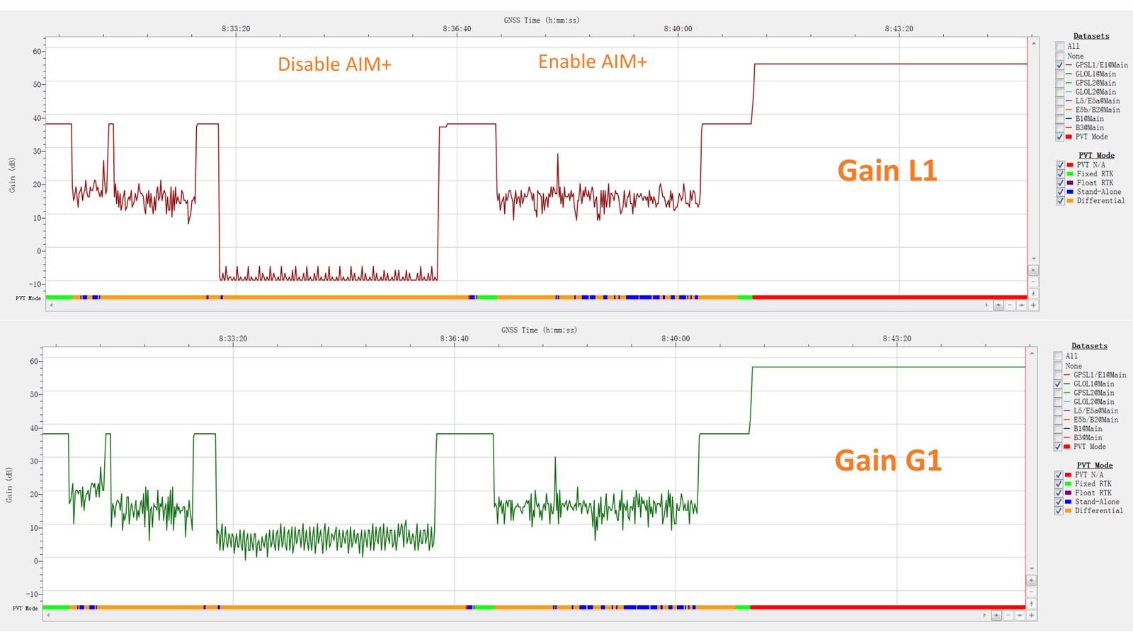
Image courtesy of Septentrio
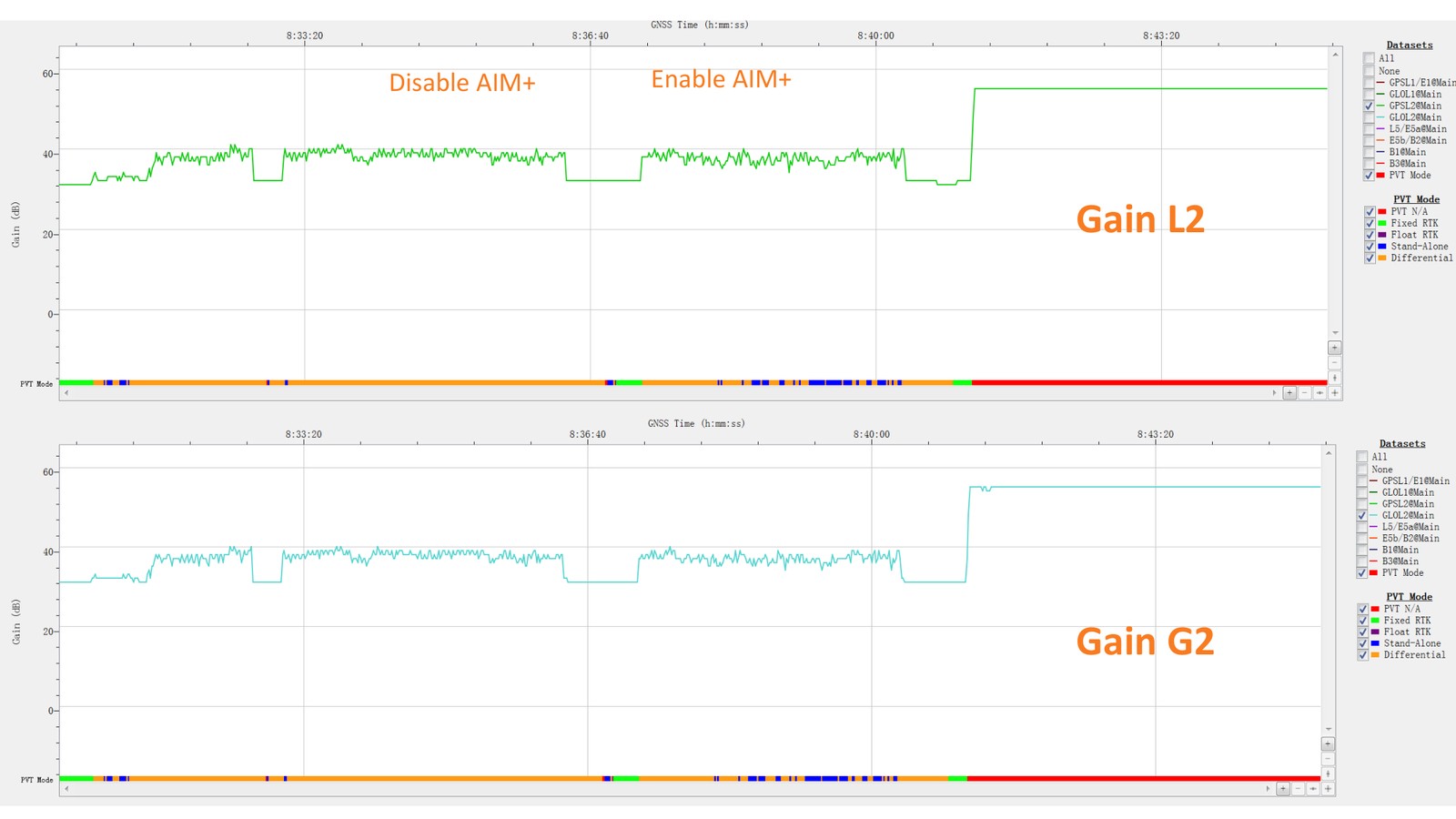
Image courtesy of Septentrio
What the receiver reports: RFStatus
The receiver reports, in real time, which bands have interference detected and whether that interference has been suppressed — for example status 8 for interference detected but not mitigated, and status 2 for interference detected and successfully mitigated. This is what turns invisible timing risk into something a monitoring system can act on before it becomes a timing error.
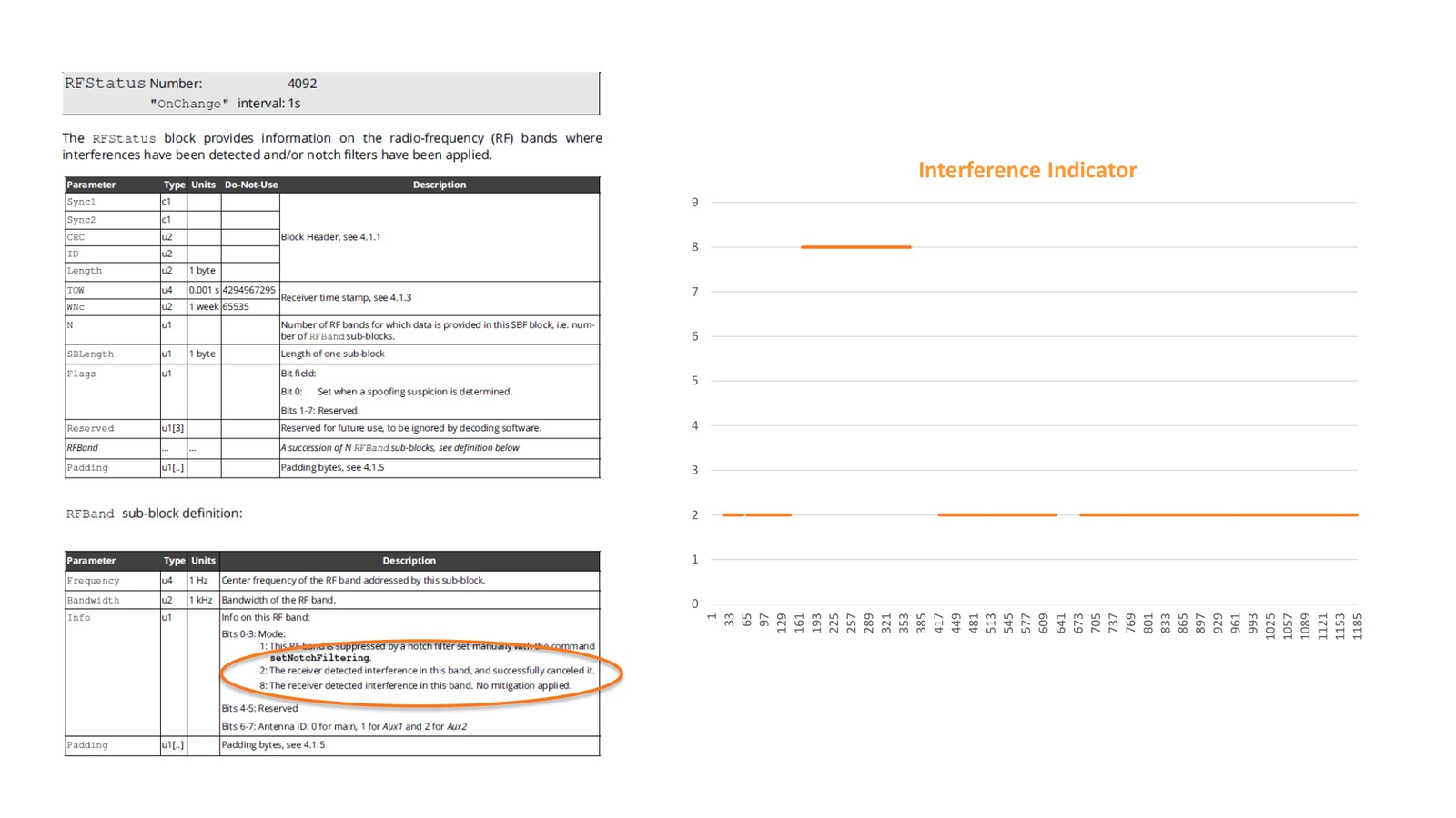
Image courtesy of Septentrio
Position and stability
In an urban canyon with an active jammer, all positions stayed within 2 m and all RTK Fix positions stayed within 1 cm. At the same time, the number of satellites tracked, the number used in the PVT solution and the velocity solution all remained stable.
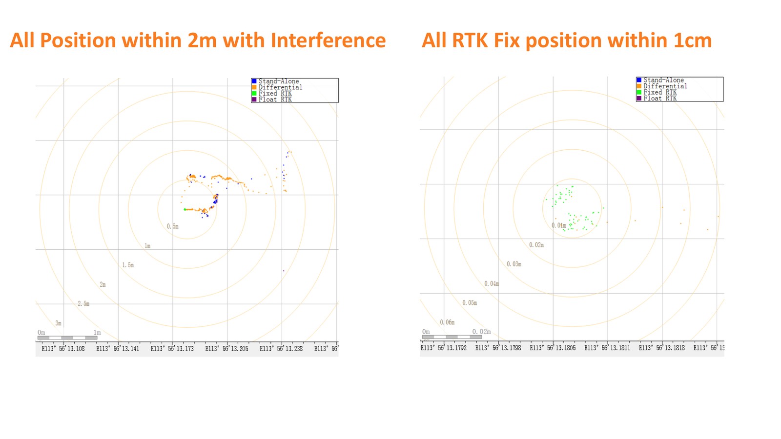
Image courtesy of Septentrio
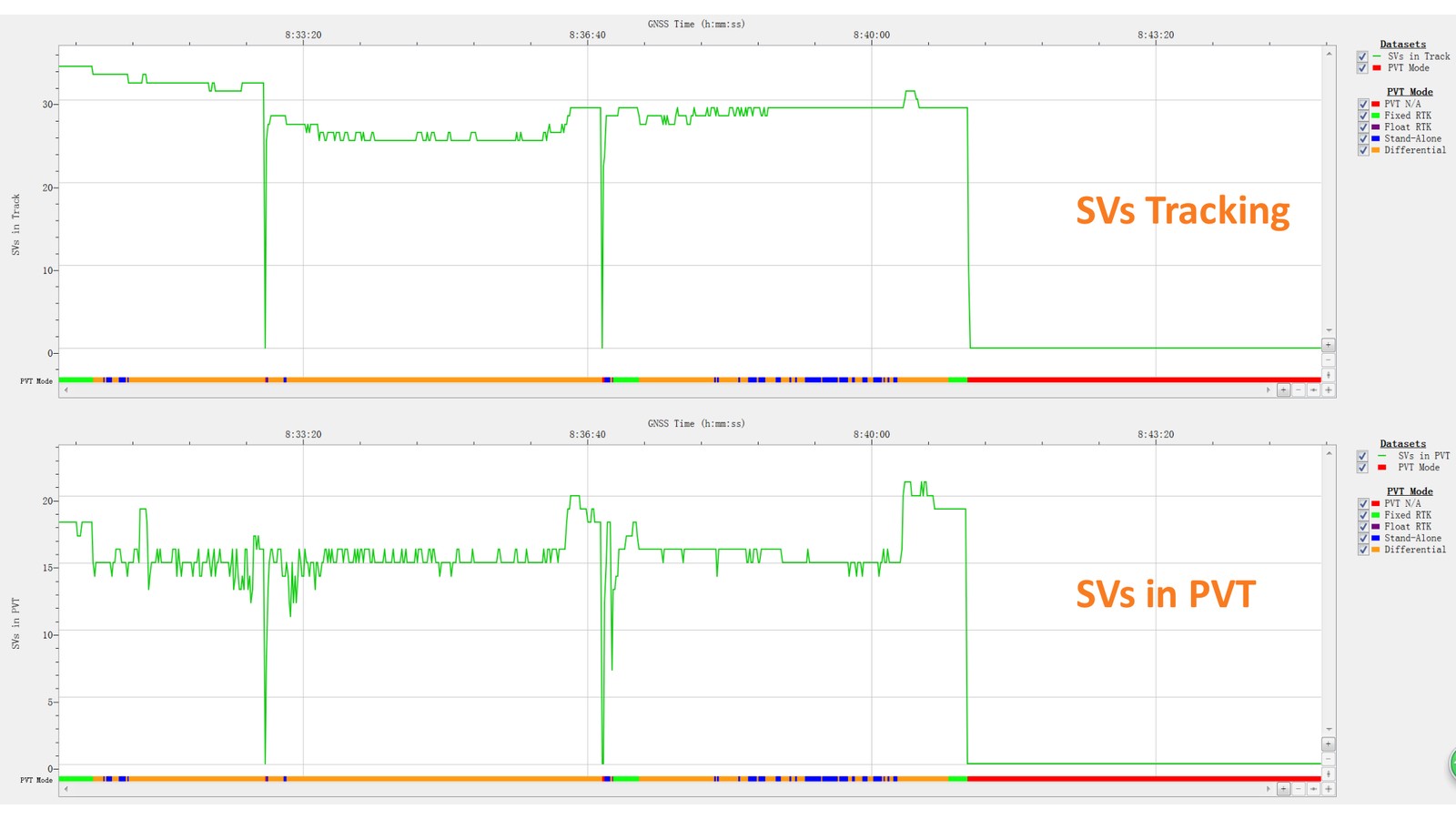
Image courtesy of Septentrio
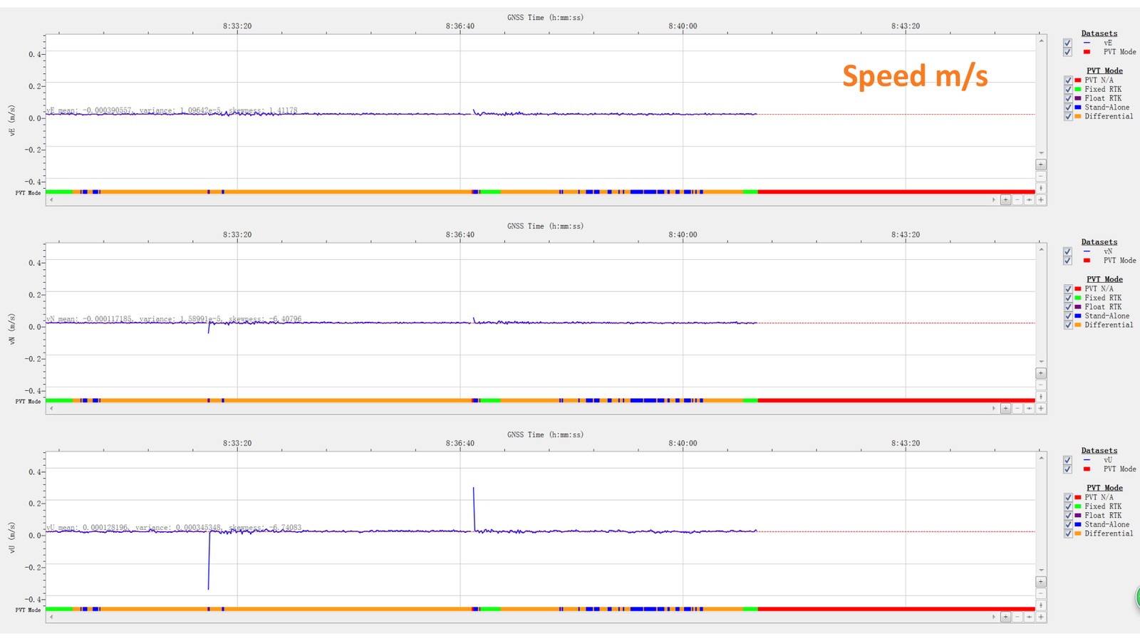
Image courtesy of Septentrio
Three conclusions come out of the test, and they are what should drive a receiver specification:
- Analog elements in the GNSS antenna and receiver introduce frequency-dependent delays into the signal processing chain;
- Traditional frequency-diversity anti-jamming can produce non-negligible PPS biases when it switches between different sets of signals;
- In-band zero-delay anti-jamming maintains a stable PPS position during jamming, by cleaning the affected frequency band rather than discarding it.
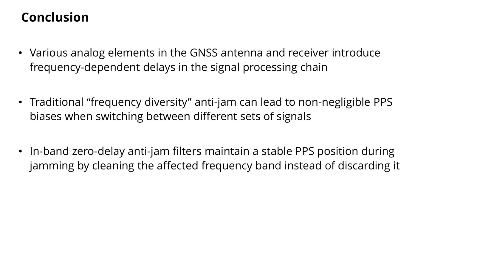
Image courtesy of Septentrio
What this means when you specify a receiver
If timing has to survive interference, the specification that matters is not only “does it have anti-jamming” but how the anti-jamming works. A receiver that cleans the jammed band in place keeps its delay constant and its PPS stable; a receiver that reacts by re-selecting signals trades timing integrity for tracking continuity.
| Specification to ask for | Why it matters for timing |
|---|---|
| In-band interference mitigation that cleans rather than switches | No delay step, so no PPS bias during a jamming event |
| Reported interference status per band | Gives monitoring systems visibility before the offset becomes a timing error |
| Specified xPPS and event accuracy | 5 ns PPS output and <20 ns event accuracy on HB56-class hardware |
| Integrity monitoring (measurement screening) | Rejects inconsistent measurements instead of letting them bias the solution |
| Anti-spoofing authentication | Spoofing is the other half of the threat model: a false reference that looks valid |
| Constant-delay, linear-phase analog chain | Turns timing behaviour into something deterministic and testable |
Two of these are worth stating plainly. First, an anti-jamming function that works by switching signal sets is not automatically timing-safe. Second, the PPS specification on the datasheet is only achieved in the interference conditions the design actually handles — which is why interference testing belongs in the acceptance criteria of a timing deployment, not in the appendix.
Eview HB56: the same technology in a receiver you can deploy
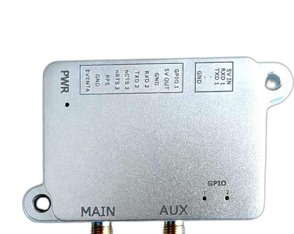
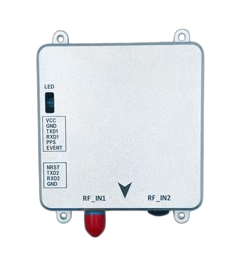
Eview GNSS builds its receivers on Septentrio engines with Septentrio Inside, so the mitigation described above ships as a receiver-level feature rather than an add-on. The HB56 is the multi-frequency receiver for this class of work: a Septentrio mosaic-X5 core with AIM+ anti-jamming and anti-spoofing, IONO+, APME+ multipath mitigation, LOCE+ and RAIM+ integrity monitoring, and a 100 Hz update rate with PPS and event outputs specified for timing use.
| HB56 — key specifications | Value |
|---|---|
| GNSS module | Septentrio mosaic-X5 — AIM+, IONO+, APME+, LOCE+, RAIM+ |
| Anti-spoofing | OSNMA support |
| Update rate | 100 Hz (moving-base RTK at 20 Hz) |
| RTK accuracy | 0.6 cm + 0.5 ppm horizontal, 1 cm + 1 ppm vertical |
| Time precision | xPPS out 5 ns, event accuracy <20 ns |
| GNSS tracking | GPS, GLONASS, BeiDou, Galileo, QZSS, NavIC, SBAS — on-board L-band |
| RTK configurations | 5-constellation RTK as base and rover |
| Interfaces | 2 × UART, USB, event marker, PPS out, SD/MMC |
| Physical / power | 7.6 × 6.9 × 1.3 cm, 60 g; 3.3 VDC, 1.6 W typical |
| Environment | −40 °C to +85 °C operating, 5–95 % humidity |
HB56 shares the mosaic-X5 core, positioning performance, 100 Hz update rate and power consumption of the HB50, with a different connector configuration to suit alternative integration layouts. Where dual-antenna heading is also needed, the HB56H adds GNSS heading on a Septentrio mosaic-H core at 20 Hz, with tighter xPPS output at 1.4 ns and event accuracy below 3 ns in a smaller 5.9 × 4.4 × 1.2 cm housing. Full configuration details are on the HB50 / HB56 multi-frequency GNSS receiver page, and the anti-jamming range is summarised under AIM+ anti-jamming receivers.
FAQ: GNSS timing under jamming
Can jamming shift GNSS time even if the position still looks fine?
Yes, and that is the central point of this article. Positioning degrades visibly when C/N0 falls, but the timing solution can move while the PPS output and its quality indicators still look normal. If your system only watches position, this failure mode is invisible to it.
What is in-band zero-delay anti-jamming?
It is interference mitigation that keeps the jammed frequency band in the signal combination and cleans it, instead of discarding the band and switching to a different set of signals. Cleaning with constant-delay, linear-phase filters keeps the delay through the chain constant, so the PPS position does not move when the jammer appears.
How accurate is the PPS on these receivers?
The HB50 and HB56 specify xPPS output at 5 ns with event accuracy below 20 ns; the HB50H and HB56H specify 1.4 ns xPPS with event accuracy below 3 ns. Those figures are what to hold a supplier to when timing is the primary output.
Is a timing receiver different hardware from a positioning receiver?
The core engine is the same class of multi-frequency receiver; the difference is what the specification emphasises. For timing, the figures that carry the risk are PPS accuracy, event timestamping, interference reporting and how the receiver behaves during an interference event.
Which Eview receiver should I use for timing in a jammed environment?
For multi-frequency positioning with 100 Hz output and PPS specified at 5 ns, the HB56 is the direct choice. If the application also needs dual-antenna heading, the HB56H adds it with a 1.4 ns PPS specification. Both carry Septentrio Inside, including AIM+ anti-jamming.
Next step
If you are specifying timing for a site, a fleet of sites or a product, send us the environment and the accuracy budget and we will come back with a configuration and a price. Contact us with your requirements, or read the companion pieces: finding and suppressing GNSS interference with AIM+, GNSS timing for 5G small cells, and RAIM+ and GNSS integrity monitoring.
Sources: Septentrio, ITSF 2025 Prague — “Stable GNSS Timing Under Jamming Attacks: Introducing Zero-Delay Anti-Jam Technology” (Jean-Marie Sleewaegen, Wim De Wilde, Samuel Heijmink), including the urban jamming-gun test on mosaic hardware. Receiver specifications from the Eview HB50/HB56 and HB50H/HB56H datasheet.