GNSS Attitude from a Moving Base: Dual-Antenna RTK Guide for Drones and Vehicles
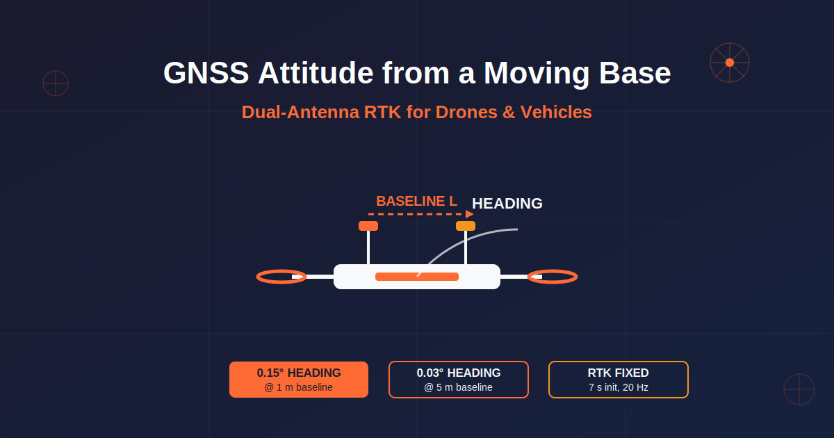
Yes — you can determine GNSS-based attitude (heading, pitch, and roll) from a moving base. A moving base receiver streams RTCM 3.x differential corrections to a rover, giving centimetre-level relative RTK positioning; with a second antenna forming a known baseline, the same RTK solution yields attitude. With the Septentrio mosaic-G5 P3H, a 1 m baseline delivers 0.15° heading accuracy (RMS), and 0.03° at 5 m.
This guide explains how moving-base GNSS attitude determination works, what hardware you need, how to set up the data link (cellular/NTRIP, UHF radio, or direct serial), how to configure base and rover receivers, and how to verify performance — for both UAV and vehicle platforms. It is based on Septentrio’s knowledge base article How to determine GNSS-based attitude from a moving base, extended with drone-specific installation guidance and verified against the official mosaic-G5 P3/P3H datasheet.
What Is a Moving Base in GNSS?
A moving base is a GNSS reference station installed on a moving platform (a vehicle, vessel, or launch platform), as opposed to a fixed ground station. The moving base sends RTCM 3.x corrections to a rover in real time, enabling centimetre-level relative positioning (RTK). When both antennas are on the same platform, the same differential solution is used to compute the platform’s attitude.
How Dual-Antenna Attitude Determination Works
Two GNSS antennas (main + auxiliary) are mounted on the platform. The line between their phase centres forms a baseline vector, whose direction in the platform body frame is known from installation calibration. Carrier-phase differential processing determines the baseline direction in the navigation frame (NED), from which attitude angles are derived:
Heading/Yaw — the baseline’s direction in the horizontal plane.
Pitch — the baseline’s tilt relative to the horizontal.
Roll — with a single baseline, roll cannot be solved independently; a third antenna (second baseline) is required.
Key physical limitation: a single baseline can solve at most two attitude angles (typically heading + pitch, or heading + roll for laterally mounted antennas). Full three-axis attitude requires a third antenna and a second baseline.
Vehicle vs. UAV: Where Moving Base Makes Sense
| Factor | Vehicle | UAV / Drone |
|---|---|---|
| Baseline length | 1–2 m or more, easy to achieve | 0.3–1 m, limited by airframe size |
| Payload & power | Ample, no strict limits | Weight, power and size critical |
| Vibration | Moderate | High-frequency propeller vibration; isolation needed |
| Multipath | Ground reflections matter | Less multipath in the air; still present at low altitude |
| Typical users | Automotive, industrial vehicles | Industrial UAVs, logistics, mapping, inspection, eVTOL |
| Attitude source | Dual-antenna GNSS + odometry/IMU | Usually IMU + magnetometer/vision; dual-antenna for high-payload precision work |
For drones, a moving base is valuable when: taking off and landing from a moving platform (ship, truck, mobile command vehicle); flying in formation where the lead drone broadcasts corrections to followers; vehicle–drone cooperation with the vehicle as the moving base; or replacing a magnetometer for reliable heading in strong magnetic interference. For lightweight consumer drones, network RTK or a static ground station remains the norm.
System Components and Hardware Requirements
Receivers
The receiver must support MovingBase mode and GNSS Attitude (e.g. Septentrio mosaic-X5, mosaic-G5, or AsteRx series). Check firmware version first — menu paths and feature support vary. For UAVs, evaluate weight, power and size (e.g. the miniature mosaic-G5 module) and reserve data-link interfaces (cellular, radio, Ethernet). A two-receiver setup (base + rover) is standard; a single receiver with integrated dual-antenna attitude and differential TX/RX is also possible.
Antennas
Use dual- or multi-frequency active antennas supporting GPS + BeiDou + Galileo + GLONASS. Main and auxiliary antennas should ideally be the same model and batch to minimise phase-centre differences. For UAVs, choose lightweight patch or short-baseline antennas; vehicles can use standard survey antennas. Ensure a good ground plane and clear signal view.
Antenna Installation
Longer baselines give better attitude accuracy (heading accuracy is inversely proportional to baseline length): vehicles ≥ 1 m, UAVs ≥ 0.3 m and as long as possible. Mount both antennas at the same height where possible, or compensate with ARP offsets. Mount rigidly (with vibration isolation on UAVs), keep clear of wings/roof edges and metal brackets, and route low-loss RF cables away from power lines and motors.
Official Performance (mosaic-G5 P3H Datasheet)
| Parameter | Value (RMS, open sky) |
|---|---|
| RTK horizontal / vertical accuracy | 0.6 cm + 0.5 ppm / 1 cm + 1 ppm |
| RTK initialisation time | 7 s |
| Update rate / latency | 20 Hz / < 10 ms |
| Attitude accuracy (1 m baseline) | Heading 0.15°, pitch/roll 0.25° |
| Attitude accuracy (5 m baseline) | Heading 0.03°, pitch/roll 0.05° |
| Interfaces | Dual UART (up to 4 Mbps), USB 2.0, 2×PPS |
| Power / size / weight | 0.44 W (P3) / 0.6 W (P3H); 22.8×16.4×2.4 mm; 2.2 g |
| Operating temperature | -40 to +85 °C |
The P3H is the dual-antenna (heading) variant; the P3 is a single-antenna high-precision positioning variant. Attitude figures assume RTK fixed solution in open sky.
Licensing and Firmware
Moving Base is a licence-controlled feature that must be activated on the receiver before use. Purchase the MovingBase (or GNSS Attitude) licence from your supplier, import the licence file with the receiver’s configuration software (e.g. Septentrio RxTools), and confirm the feature status shows Active. Update firmware to the minimum supported version before activation.
Data Links: Cellular, Radio, or Direct Connection
The data link is the core of a moving-base setup: the base streams RTCM 3.x to the rover (one-way, base → rover). Two message groups matter:
1005/1006 — base station coordinates (mandatory for integer ambiguity resolution; send every 1–10 s).
MSM observation messages — 1074/1077 (GPS), 1084/1087 (GLONASS), 1094/1097 (Galileo), 1124/1127 (BeiDou); MSM4 is medium precision, MSM7 high precision.
Bandwidth reference: MSM4 all constellations ≈ 1–3 kbps at 1 Hz; MSM7 ≈ 3–8 kbps at 1 Hz. For high-dynamics UAVs, use MSM7 at 5–10 Hz and keep end-to-end latency below ~1 s. When base and rover are on the same platform (typical dual-antenna attitude), a direct serial connection is enough — no cellular or radio needed.
Cellular (4G/5G + NTRIP)
Best for long range, no line-of-sight, and multi-vehicle operations. Architecture: base 4G/5G modem → NTRIP caster → rover 4G/5G modem. Configure SIM/APN, caster address and port (default 2101), credentials, mountpoint, and RTCM 3.x format. Public-network latency is about 50–200 ms, fine for RTK (< 1 s budget); packet loss causes frequent RTK outages, so critical operations should use fixed IP/leased lines or carrier QoS. Multiple rovers can share one mountpoint — ideal for drone swarms.
UHF/VHF Radio
Best for line-of-sight, no-public-network, low-latency and confidential operations. Architecture: base TX radio + antenna → rover RX radio. Typical bands: UHF 433 MHz (China, limited power for licence-free devices), 868/915 MHz (EU/US); VHF 220 MHz travels further with larger antennas. Range: ~1–5 km at 1 W, ~10–50 km at 5–35 W (terrain and antenna height matter more than power). In China, high-power 433 MHz radios require a radio station licence — confirm compliance before use.
Direct Serial / LAN
Serial (COM) direct — recommended for same-platform attitude: connect base and rover UARTs (mosaic-G5 provides dual UART up to 4 Mbps), matching baud rates.
Ethernet TCP/UDP — base as TCP server (or UDP), rover as client; configure IP and port.
Wi-Fi LAN — short-range ground vehicle or ground-station scenarios.
RTCM Message Configuration
| Message | Content | Suggested rate |
|---|---|---|
| 1005/1006 | Base station coordinates (ITRF/WGS84) | 1 per 1–10 s |
| 1074/1077 | GPS observations (MSM4/MSM7) | 1–10 Hz |
| 1084/1087 | GLONASS observations | 1–10 Hz |
| 1094/1097 | Galileo observations | 1–10 Hz |
| 1124/1127 | BeiDou observations | 1–10 Hz |
| 1033 | Antenna description (optional) | 1 per 30 s |
For high-dynamics UAVs, use MSM7 at 5–10 Hz; for static/slow vehicles, MSM4 at 1 Hz is sufficient. Keep all constellation rates consistent.
Configuration Steps
Base Receiver
Set the receiver to Moving Base / Base Station mode, connect the main antenna (forward antenna recommended), configure RTCM 3.x output messages and rates, and confirm the data link is transmitting.
Rover Receiver
Set Positioning Mode to GNSS Attitude with attitude mode MovingBase. Configure main + auxiliary antennas, enter the baseline length (or let the system auto-calibrate), and configure the RTCM input to match the base (NTRIP mountpoint / radio frequency / TCP port). Attitude output is only valid once the rover reaches RTK fixed.
For non-default antenna layouts, compensate in the GNSS Attitude control panel: method 1 — enter the auxiliary antenna’s X/Y/Z coordinates relative to the main antenna ARP (e.g. forward along X: X = 1.0 m, Y = 0, Z = 0; lateral: Y = 1.0 m); method 2 — enter heading/pitch offset angles. Wrong axes or signs produce incorrect attitude that is hard to debug.
Output and Parsing
AttEuler (SBF) — binary message with heading, pitch, roll and solution status (fixed/float/invalid); recommended for flight controllers.
HDT (NMEA) — $HTHDT,
HRP (NMEA) — $PASHHRP,
Attitude is only reliable with an RTK fixed solution; float solutions show degraded accuracy. Always use the status flags.
Testing and Verification
Static test: compare computed heading with a known reference (compass/gyro/total station). Dynamic test: drive/fly straight and compare track direction with output heading; observe attitude response during turns/pitch manoeuvres. Link test: watch RTK status (Fixed), RTCM reception counts, latency and packet loss. For UAVs: initialise on the ground before take-off; heading should remain stable during hover.
Accuracy vs. Baseline Length
| Baseline | Heading accuracy | Pitch/roll accuracy |
|---|---|---|
| 1 m | 0.15° | 0.25° |
| 5 m | 0.03° | 0.05° |
Heading accuracy is roughly inversely proportional to baseline length — halving the baseline roughly doubles the heading error (confirmed by datasheet: 0.15° × 1 m = 0.03° × 5 m). For intermediate baselines (e.g. 0.3 m), estimate by the inverse relationship or verify by measurement.
Frequently Asked Questions
What is a moving base in GNSS RTK?
A moving base is a GNSS reference station mounted on a moving platform (vehicle, vessel, launch platform) instead of on the ground. It streams RTCM 3.x corrections to a rover in real time, enabling centimetre-level relative positioning. When both antennas sit on the same platform, the same differential solution also yields the platform’s attitude (heading, pitch, roll).
How does GNSS attitude determination from a moving base work?
Two antennas form a baseline whose direction is known in the platform body frame from installation calibration. Carrier-phase differential processing (RTK) resolves the baseline direction in the navigation frame (NED), from which heading and pitch are derived. Roll needs a third antenna / second baseline.
What accuracy can I expect?
With the Septentrio mosaic-G5 P3H and RTK fixed solutions in open sky: heading 0.15° RMS with a 1 m baseline and 0.03° RMS with a 5 m baseline; pitch/roll 0.25° at 1 m and 0.05° at 5 m. Accuracy scales roughly inversely with baseline length.
Do drones really need dual-antenna GNSS for heading?
Only for demanding operations: large-payload precision work, moving-platform take-off/landing, swarm coordination, or strong magnetic interference where magnetometers fail. Lightweight consumer drones typically use network RTK or static base stations with IMU-based heading.
What RTCM messages should a moving base send?
Always send 1005/1006 (base coordinates) every 1–10 s, plus MSM observation messages: 1074/1077 (GPS), 1084/1087 (GLONASS), 1094/1097 (Galileo), 1124/1127 (BeiDou). Use MSM7 at 5–10 Hz for high-dynamics UAVs, MSM4 at 1 Hz for slow vehicles.
Is MovingBase mode free, or does it need a licence?
Moving Base and GNSS Attitude are licence-controlled features on Septentrio receivers. You must purchase the licence, import the licence file (e.g. via RxTools), and confirm the feature is Active before attitude output works.
What data link should I use between base and rover?
Same-platform attitude setups use direct serial (COM) connection. Long-range or multi-vehicle operations use cellular NTRIP (50–200 ms latency) or UHF/VHF radio (low latency, no public network, licence rules apply). Choose by range, latency, coverage and confidentiality requirements.
Build Your Moving Base System with Eview GNSS
Eview GNSS supplies Septentrio-powered receivers including the mosaic-G5 P3/P3H and OEM boards for drones and vehicles. Our engineers can help you select antennas, plan the data link, and configure MovingBase + GNSS Attitude for your platform. Explore UAV RTK solutions or contact our team for a project consultation.
Sources & References
Author: Eview GNSS / Nanjing Hongcheng Intelligent Technology Co., Ltd.
Published: August 18, 2026
External references:
- Septentrio Knowledge Base: How to determine GNSS-based attitude from a moving base — septentrio.com
- Septentrio Knowledge Base: How to get RTK positioning using a moving base
- ESA Navipedia, RTK Systems — gssc.esa.int/navipedia
- Septentrio mosaic-G5 P3/P3H official datasheet (accuracy figures)
- Giorgi et al., “Attitude Determination”, Springer Handbook of Global Navigation Satellite Systems, Ch. 27, 2017