RTK Base Station Setup Guide: Receiver, Antenna, Position
What makes an RTK base station correct? Four decisions, in this order: a receiver that is licensed to output corrections and tracks the signals your rovers use, an antenna with a known calibration, a mount that does not move, and — the one people get wrong — a reference position that is absolute rather than merely self-consistent. Get the first three right and a rover will still report a different coordinate for the same point if the fourth is left on auto.
Quick answer: Build the base station around a receiver with the RTK Base capability enabled, give it an antenna with a calibration file, and set the reference position from a known marker, an online PPP solution or an averaged RTK fix — never from the auto function in production. Only an absolute reference position lets rover data from different base stations be compared at all. Configure the output as RTCMv3 MSM4 at 1 Hz and save the whole setup to the boot configuration.
This guide follows Septentrio’s six-chapter technical note How to set up a base station, including the worked example in which one PolaRx5e receiver and one VeraPhase 6000 antenna are used to compute three different reference positions — and then three rovers are plotted side by side to show what the choice actually costs. All figures are reproduced from that document.
What an RTK base station actually does
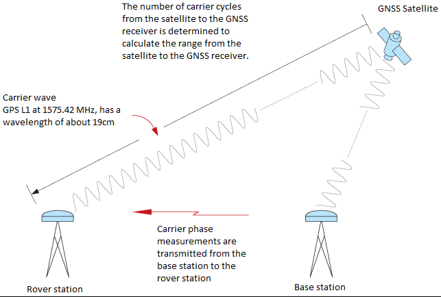
In RTK, the rover resolves its position to the centimetre by correcting the carrier-phase measurements it receives against a nearby reference. The base station’s job is to supply those corrections — and, more subtly, to define the coordinate frame in which the rover’s answer means something.
Baseline length, the distance between rover and base receiver, is the first accuracy lever. Differential techniques assume the two stations see broadly the same atmosphere; the longer the baseline, the less that assumption holds, and the practical limit depends on how active the local ionosphere typically is. Short baselines are the reason a base station is usually placed near the centre of the working area, and the reason large sites (tens of kilometres) are covered with several base stations rather than one high-power radio link.

Location and position are not the same thing
Two words get used interchangeably and should not be. Location is the physical place the antenna is installed — normally open sky, a roof or a clear field. Position is the coordinate that is typed into the receiver and expressed in a reference frame such as WGS84.
The distinction matters because it produces the difference between absolute and relative positioning. In absolute positioning the base coordinates are known in a reference frame (for GNSS, usually WGS84 or an equivalent datum), so observations from rovers working off different base stations can be compared with each other — provided those base stations use the same datum. The more accurate the base coordinates are, the more trustworthy that comparison becomes. In relative positioning the base station’s own place in the frame is not precisely known: rover results are consistent with each other as long as they use that one base, but they cannot be compared with data from anywhere else.
Because a global frame is not always the best way to compare positions locally, many national and regional frames exist, each valid within its own area. Switching frames without the correct transformation is what produces the position jumps operators notice when they change coordinate systems.
Choosing the receiver: two checks before anything else
Almost any modern multi-frequency receiver can act as a base. The range runs from dedicated reference receivers such as the PolaRx5, through compact integrated units aimed at network and network-encryption work such as the AsteRx SB3 ProBase, to easy-to-use all-in-one survey products. OEM boards such as the AsteRx-m3 ProBase and modules such as the mosaic-X5 make equally good base stations once integrated.
Two properties decide whether a given unit will do the job.
1. It must be permitted to output corrections
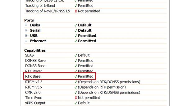
Correction output — RTK Base in Septentrio’s terminology — is a licensed capability. Check the receiver’s permitted capabilities before planning anything; a unit that runs fine as a rover may not be enabled to transmit RTCM.
2. It must track the signals the rovers actually use
Start from the rover side: list the constellations and signals your rovers will run, then confirm the base can generate corrections for them. Not every signal is usable for RTK. As a rule, the more signals the base can supply corrections for, the better the chance that connected rovers reach a reliable fixed solution — which is why multi-frequency, multi-constellation base hardware has become the default rather than a premium.
Choosing the antenna
Three questions decide the antenna: size and weight, whether the installation is permanent, and whether a relative or absolute calibration is available for that exact model.
For static work, a choke-ring antenna is the best-performing option: it suppresses multipath most effectively and usually ships with an absolute calibration. Where position accuracy comes before cost, that is the choice. In many cases a good geodetic antenna such as the PolaNt-x MF is entirely sufficient, and for non-permanent installations a receiver with an integrated antenna — a so-called smart antenna — can be an interesting alternative.
Mounting options range from tripods and magnetic poles to welded or concrete pillars. Whatever the choice, rigidity is the property that matters: a base station that moves between sessions produces a new reference position even when nothing else changed, and every downstream coordinate shifts with it.
Installing the antenna
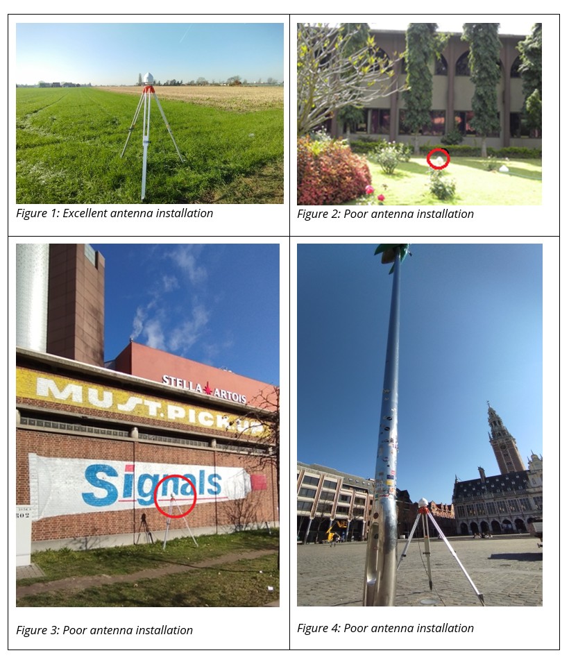
The installation rules are short but they decide whether the rest of the setup can work. Put the antenna under open sky, away from anything that blocks the direct path to the satellites. A roof or a tripod in a clear field is typical; a magnetic mount on a stationary vehicle is acceptable for testing and evaluation.
Keep the mount rigid against wind, weather and incidental contact, and keep the antenna clear of transmitters — LTE base stations and satellite uplink equipment being the two usual offenders. The antenna itself must stay vertical, and the connector must not carry the cable’s weight. Permanent installations should include a surge arrester. Cable choice matters as well: beyond roughly 20 metres of run, low-loss cable stops being optional, and in some environments (marine, for instance) the antenna and connector need extra protection such as cold-shrink sleeving.
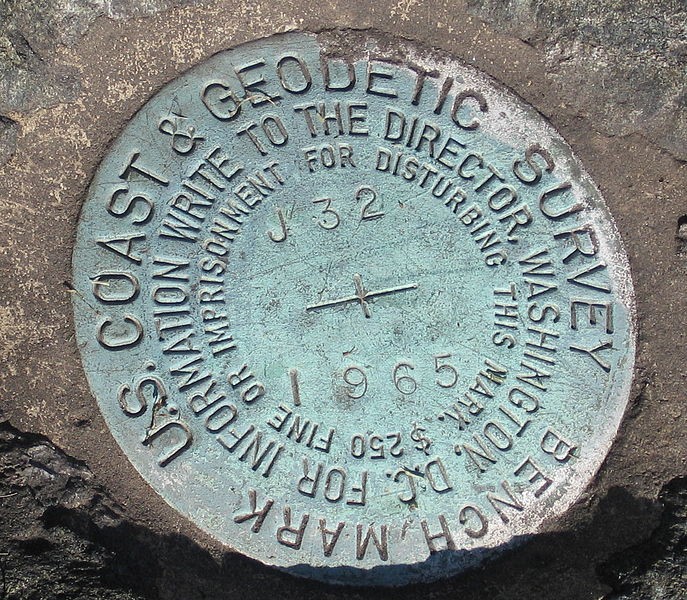
If the reference position will come from a known marker, the antenna has to sit exactly over that marker, with the height difference measured and compensated in the receiver.
Determining the reference position
This is the chapter that separates a base station that produces usable survey data from one that produces numbers nobody can compare. There are four methods. They differ less in whether they can produce a position than in whether that position is absolute, whether it can be reproduced later, and how long it takes to obtain.
Known reference point
The fastest reliable method when one exists: put the antenna over a geodetic control point or survey marker, using a tribrach and tripod for precision, and enter the marker’s geodetic or Cartesian coordinates into the receiver’s reference position fields. The marker’s coordinates must be accurate and current — an old published coordinate is worse than no coordinate, because it looks authoritative. Then compensate the height between the marker and the antenna’s reference point by entering the marker-to-ARP offset and selecting the correct antenna type. Skip that step and the phase-centre offset lands directly in the corrections.
Online PPP post-processing
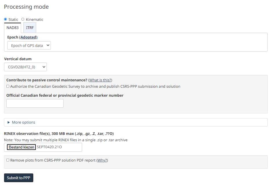
With no marker available, an online precise point positioning service can compute the antenna’s position. NRCan’s CSRS-PPP, OPUS and APPS are the usual options, each with its own rules on data format, session length and content. Most ask for at least one to three hours of data and prefer 24; nearly all want RINEX, at differing versions. The most accurate solution appears only after a delay — typically a day, up to two weeks.
The published coordinate is an absolute reference position: every rover measurement recorded by that base afterwards refers to the PPP service’s absolute frame. For a permanent installation, a 24-hour log is not an optimisation, it is the requirement.
Averaged real-time RTK fix
When there is no control point and no time to wait for PPP, but an RTK service or another base station is reachable, the receiver can determine its own reference position from RTK. Set the future base to act as an RTK rover, let it compute fixed positions against the existing service, record them and average. This needs the RTK Rover capability enabled on that receiver. The averaging can be done after the fact: PVTGeodetic and PVTCartesian are recorded as SBF blocks, converted to ASCII with SBF Converter, and averaged in Excel, R or Python.
The caveat is the frame: the averaged coordinate is expressed in the datum of the base station or network used, which may not be the datum wanted for the final reference position.
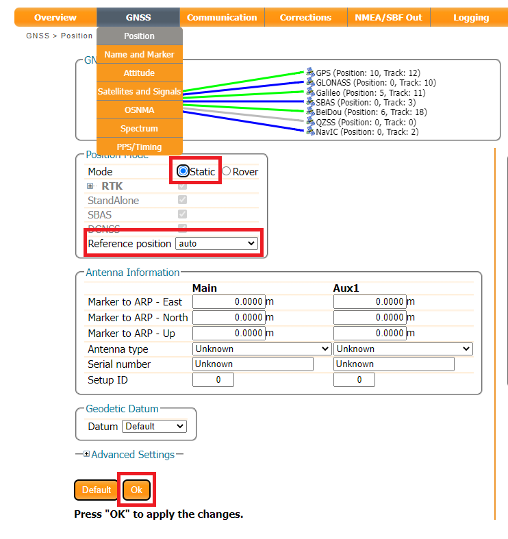
The auto function
In static mode a receiver can be told to take the first position it considers valid as its reference, with all measurements referred to that point. The position may be a standalone, SBAS, PPP or RTK solution, so its accuracy depends entirely on which mode the receiver happened to be in at that moment.
Rover accuracy relative to that base is comparable to what an absolute reference position would give. What is lost is comparability: the base has no accurate place in the frame, so its rovers cannot be compared with rovers working off a different base. And every restart computes a new auto position, so the same field procedure produces a different coordinate set next week. That combination is why auto belongs to evaluation and testing, not to production.
A relative position can be converted to an absolute one later — recompute the base position, for example from RINEX of a local reference network using post-processing software such as Septentrio’s PPSDK, then recompute the rover measurements against the updated base position. The cost is that every rover dataset has to be reprocessed.
The four methods side by side
| Method | Prerequisites | What you get | Where it breaks |
|---|---|---|---|
| Known reference point | Accurate, current control point; antenna centred over the marker; height measured and compensated | Accuracy limited only by the marker’s coordinates — and it is the fastest route | Marker-to-ARP offset and antenna type must both be entered, or the phase-centre offset enters the corrections |
| Online PPP post-processing | A PPP service (CSRS-PPP, OPUS, APPS); at least 1–3 hours of data, ideally 24; usually RINEX | Absolute position, highest accuracy available | Result arrives after a day to two weeks; permanent sites need the full 24-hour log |
| Averaged RTK fix | A reachable RTK service or base; the receiver must hold the RTK Rover capability | High-accuracy reference position within a short session | Coordinates inherit the datum of the service or network used |
| Auto function | Static mode with auto enabled | The first position the receiver accepts; accuracy follows the mode it was in | Not reproducible after a restart and not absolute — evaluation only |
In one line: if the coordinates have to be comparable with anyone else’s, use a known point, PPP or an averaged RTK fix. If only internal consistency matters, auto is workable — as long as everyone involved knows the position is not reproducible.
Configuring the RTCMv3 correction output
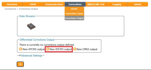
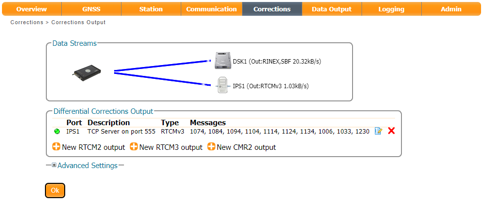
With a reference position in place, the base needs an output stream. In the web interface that is Corrections > Corrections output > New RTCMvX output, followed by a choice of connection type. A serial port is the common case; IP, NTRIP and the internal caster all follow the same logic.
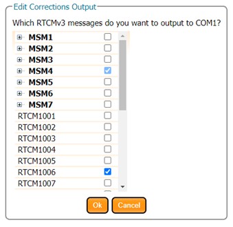
Use RTCMv3, not RTCMv2 or CMR2. RTCMv2 is a legacy format built on fixed-length packets: less compact, no BeiDou or Galileo corrections, and no support for many modern message types. CMR, CMR+ and CMR2 are Trimble’s closed proprietary formats whose message definitions are not all public, so compatibility with third-party receivers cannot be guaranteed in every case.
On current Septentrio receivers, selecting RTCMv3 messages proposes MSM4 for all four constellations automatically:
| Message | Content |
|---|---|
| RTCM1074 | GPS MSM4 |
| RTCM1084 | GLONASS MSM4 |
| RTCM1094 | Galileo MSM4 |
| RTCM1124 | BeiDou MSM4 |
| RTCM1006 | Station description (ARP and antenna height) |
| RTCM1033 | Receiver and antenna description |
| RTCM1230 | GLONASS L1 and L2 code-phase biases |
Older receivers do not select MSM4 automatically and fall back to legacy messages:
| Message | Content |
|---|---|
| RTCM1004 | Extended GPS observations (L1 and L2) |
| RTCM1006 | Station description (ARP and antenna height) |
| RTCM1012 | Extended GLONASS observations (L1 and L2) |
| RTCM1033 | Receiver and antenna description |
| RTCM1230 | GLONASS L1 and L2 code-phase biases |
Switching to MSM4 manually is possible, and worth adding 1006, 1033 and 1230 as general-purpose messages. Exact message behaviour per model is in the receiver’s firmware reference manual.
Output rate
1 Hz is the right rate for real-time base corrections. Raising or lowering it requires detailed GNSS knowledge and is not something to tune casually. Bandwidth is the constraint that bites: more messages at a higher rate means more throughput, which is a real problem on capacity-limited links such as UHF. Work out the stream’s bandwidth requirement and check the link against it before commissioning.
Worked example: one antenna, three reference positions
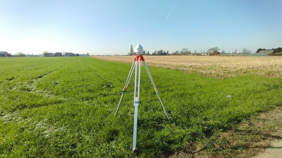
Septentrio’s example uses a PolaRx5e connected to a VeraPhase 6000 antenna under open sky, and computes three different base positions for that single location: an online PPP solution from six hours of Support SBF blocks (24 hours recommended for best results), an average of six hours of RTK fixed positions with the receiver temporarily acting as an RTK rover, and the auto function.
Each reference position is written into the same receiver, which is then set to static mode and configured to output RTCM. Rover positions recorded against each configuration are plotted together at the end of this section.
Method A — online PPP
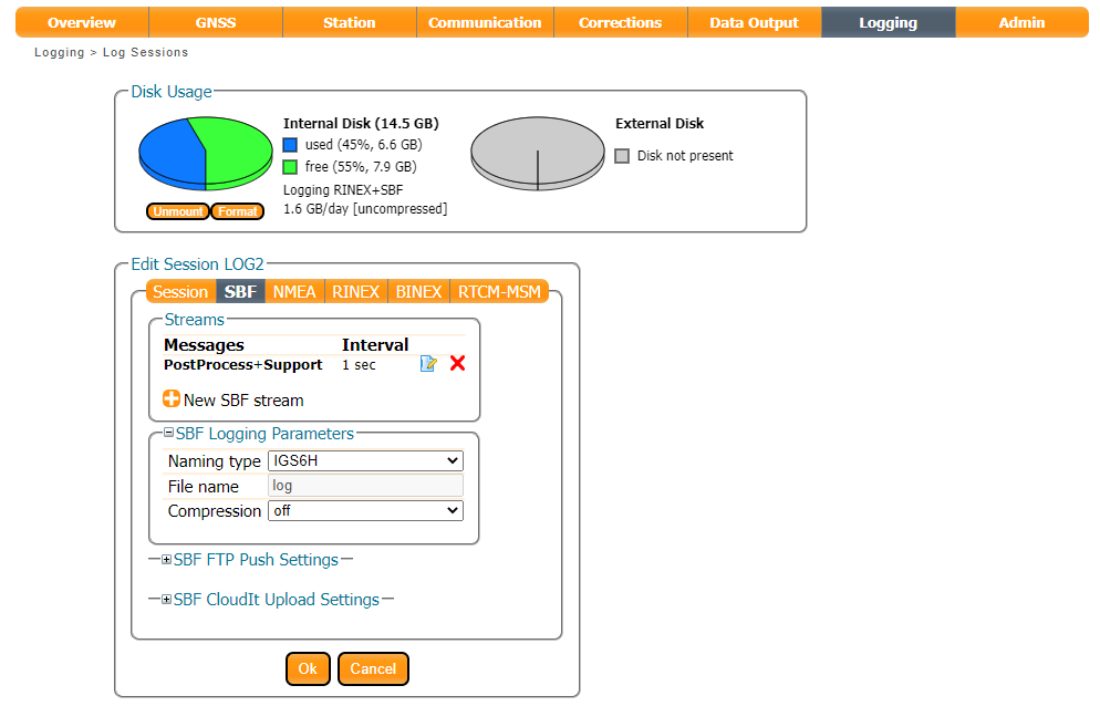
A logging session is started with the predefined Support SBF block set, which contains everything needed to convert to RINEX for post-processing (the PolaRx5 and PolaRx5e can also log RINEX directly). The IGS6H file-naming convention keeps all base data in a single file, which is what the PPP service wants.
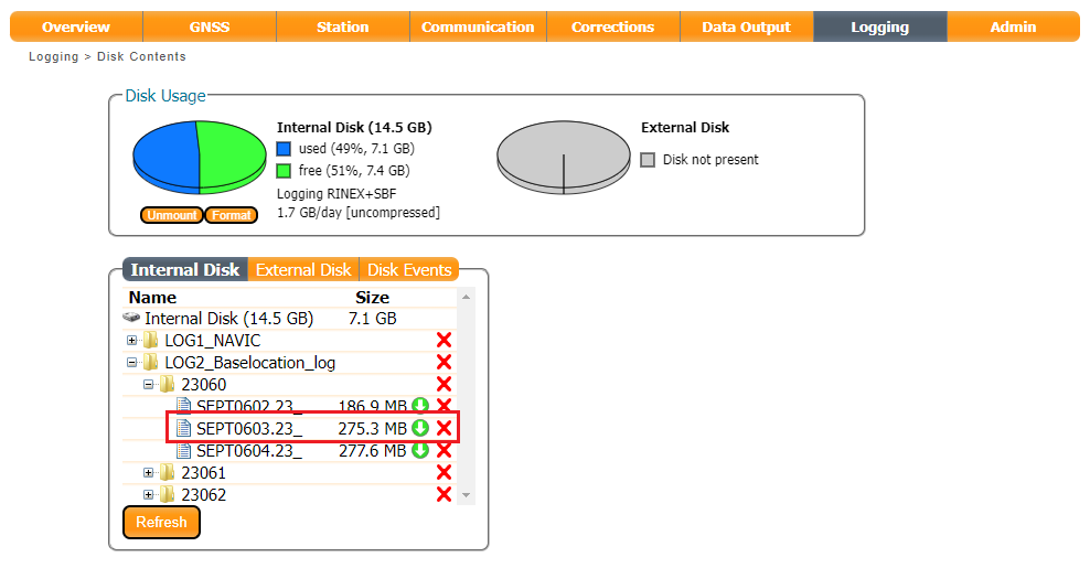
After at least an hour (the minimum this service accepts; six hours were recorded here) the log is downloaded, converted with SBF Converter and submitted.
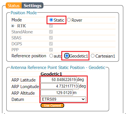
The service returned the corrected position the following day:
| Latitude | Longitude | Ellipsoidal height |
|---|---|---|
| 50.84862262 | 4.732126167 | 129.012 |
Those coordinates go back into the PolaRx5e, the RTCMv3 output is configured, and the configuration is saved to the receiver’s boot configuration so it survives a power cycle.

Method B — averaged RTK fix
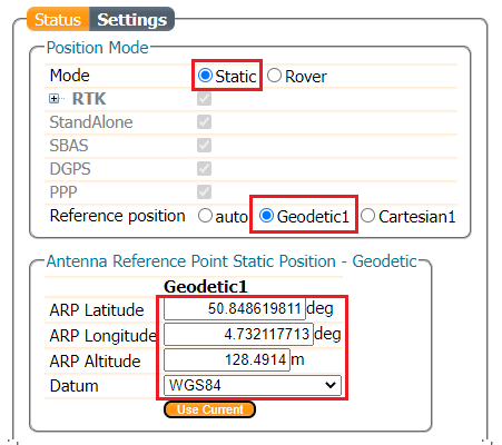
The same antenna and receiver, a new logging session, six hours of data, and the RTK fixed positions extracted from PVTGeodetic. The average becomes the reference position:
| Latitude | Longitude | Ellipsoidal height |
|---|---|---|
| 50.84861981 | 4.732117713 | 128.4914 |
Method C — auto
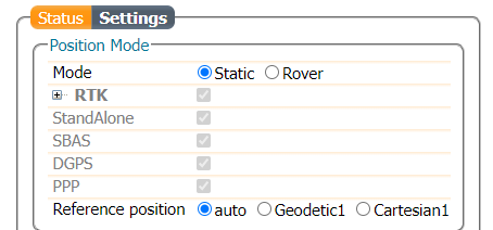
The receiver is set to static mode with the static position set to auto, then the RTCMv3 output and boot configuration are set up exactly as before.
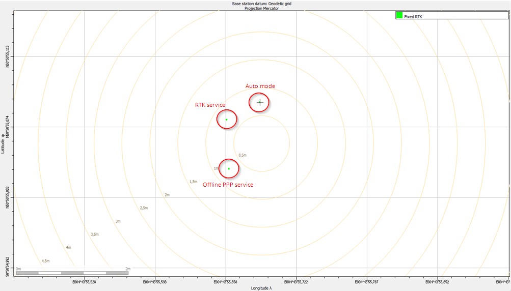
What the rovers reported
Three rover datasets, one antenna, one location — and three different answers. RTK performance is excellent in all three sets; the differences come entirely from the reference positions behind them.
The lower-left cluster is the rover working off the PPP-derived base position. These coordinates are absolute in WGS84 and can be compared with any other data expressed in the same frame, including other base stations and RTK services.
The upper-left cluster comes from the RTK-averaged reference position. Also absolute, but in ETRS89 — comparable with other ETRS89 data, such as results from the same RTK service, not with WGS84 data without a transformation.
The upper-right cluster is the auto configuration. The frame is nominally the base’s WGS84 datum, but because the auto position carries an unknown error, the base is not absolute: these rover results can be compared with each other, and with anything else computed from the same base’s corrections, but not with the absolute results from the other two methods.
Frequently asked questions
Do I need a choke-ring antenna for a base station?
No. A choke-ring antenna is the best choice where position accuracy is the priority — best multipath rejection, usually with an absolute calibration — but a good geodetic antenna such as the PolaNt-x MF performs well enough in many installations, and a non-permanent base can use a receiver with an integrated antenna.
PPP or averaged RTK: which should I use?
Both give an absolute reference position. PPP needs one to three hours of data (24 for permanent sites) and returns the answer after a day to two weeks. Averaged RTK needs a reachable service or base and delivers in a short session, but the coordinates inherit that service’s datum. No control point and no deadline: use PPP. Service available and the site has to be finished today: average RTK. For a permanent installation, use both — the RTK average to start work, the PPP solution as the final coordinate.
Why RTCMv3 instead of RTCMv2 or CMR2?
RTCMv2 uses fixed-length packets, is far less compact, carries no BeiDou or Galileo corrections and lacks many modern message types. CMR, CMR+ and CMR2 are closed proprietary formats, so third-party compatibility cannot be guaranteed for every message.
What output rate should the corrections run at?
1 Hz. Changing it requires real GNSS expertise and is not recommended. Bear in mind that more messages at a higher rate consume more bandwidth, which matters on UHF and other capacity-limited links — verify the stream fits the link before deployment.
Can the auto function be used in production?
Not recommended. It takes the first position the receiver considers valid, its accuracy depends on the mode at that moment, it is recomputed at every restart, and it leaves the base without an accurate position in the frame. Use it for evaluation and testing; production needs a high-accuracy reference position.
Why can’t rover positions from two different base stations be compared?
Because each rover result is relative to its own base’s reference position. If both bases are absolute — known point, PPP or RTK average — the datasets are comparable, subject to using the same datum. If either base used auto, its results are only comparable with data computed from that same base’s corrections.
What is the difference between location and position in this context?
Location is where the antenna physically is: a roof, a field, a tripod. Position is the coordinate entered into the receiver, expressed in a reference frame such as WGS84. The same location can be given several different positions — which is exactly what the worked example above demonstrates.
Hardware for a base station like this
If the job is to build a base station rather than specify one from a catalogue, the receiver choice narrows quickly. The Eview HB62 is a rugged base and reference receiver built on the Septentrio mosaic-X5: multi-frequency, all constellations, and correction output over Ethernet, NTRIP or a serial radio link — the RTK Base capability this guide assumes is enabled as standard. Where the same site also needs recording or heading, the HB56 and HB56H add SD logging, and the HB10 covers dual-antenna heading on the AsteRx-m3 Pro+ platform. For a permanent installation, pair the receiver with an antenna that carries an absolute calibration.
Three checks before commissioning, whatever the hardware: the receiver is licensed for RTK Base output, the antenna model and its calibration match what was entered in the receiver, and the reference position came from one of the three absolute methods rather than auto.
Talk to an engineer about your base station. If you are specifying a reference station — permanent CORS-style, a temporary site base for a survey campaign, or a base feeding several rovers — send the site conditions and the rover hardware, and we will come back with a receiver and antenna configuration. Request a quote or use the contact form.
Sources
Septentrio Customer Support, How to set up a base station, chapters 1–6 — customersupport.septentrio.com. All figures and the coordinate values in Tables 4 and 5 are reproduced from that document. Product specifications referenced here are Septentrio’s.